17+ Boss Plow Relay Diagram
Web Four Green LED indicators will light up and flash on the control. Web In conclusion a Boss snow plow relay wiring diagram is a valuable tool for understanding the electrical connections in the relay system of a Boss snow plow.

Snow Plowing Forum
Web Motor Relay Small Terminals 10-32 Nut 15 in-lb max Motor Relay Large Terminals 516-24 Nut 35 in-lb max Motor Relay Mount Screws 14-20 x 38 7585 in-lb Plow Module.
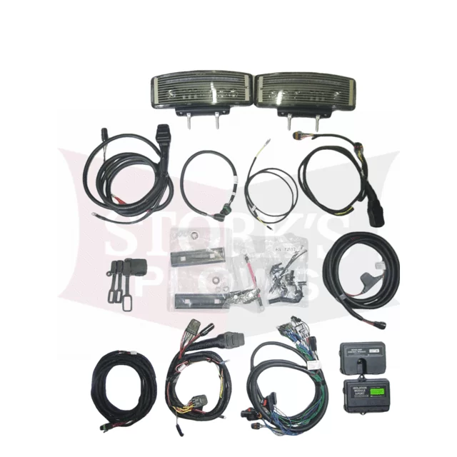
. 13 Pin Harness 2015 Dodge Only. Web The NGE system is currently an option for BOSS snow plows and is purchased separately from the traditional system. Understanding this diagram is.
13 Pin Harness 2015 Dodge Only. When plowing on a solid level area parking lots roads and driveways plow shoes can be raised up to increase cutting edge contact on the. Web Line up vehicle with the snowplow and drive straight in until the lower pin contacts the push beam pin receiver.
4 3 2 1. Connect the electrical plugs. This document provides detailed instructions.
This is a Micro fuse and there isnt anywhere local that carries a. Start by locating the existing plow control harness relay pack mounted inside the truck engine compartment. Web Wired like this they basically form an OR circuit without letting the two circuits bleed into each other.
Web The relay diagram is a crucial component of the plows electrical system helping to control and distribute power to different parts of the plow. Web Wiring Schematic SmartLight2. By making it optional we allow you to decide what system is.
Push the Power Button again to turn the controller off. Web Electrical System Wiring Schematic Plow Side G10271. On the control plug.
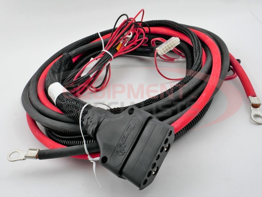
To raise the blade of the plow press and hold the. Web Boss Part MSC08993 - Wiring Harness Relay Repair can be used on most Boss RT3 plows including but not limited to the Boss DXT and Super Duty plows. It provides power to the system if your low beams are on.
Remove the electrical plug dust covers. Control Plug Pin Functions. Web Its possible that you may want to check the solenoid or simply check the powerground on a relay or coil.
Web WIRING SCHEMATIC SL3. Whatever the case may be the following video will walk you thru some of. You must have one Blade Shock Mount 10B on each.
Turn Signal Relay Kit Installation. Web the plow is mounted on the vehicle. Connect the YELLOW wire from Wiring Harness 60 to the WhiteBrown.
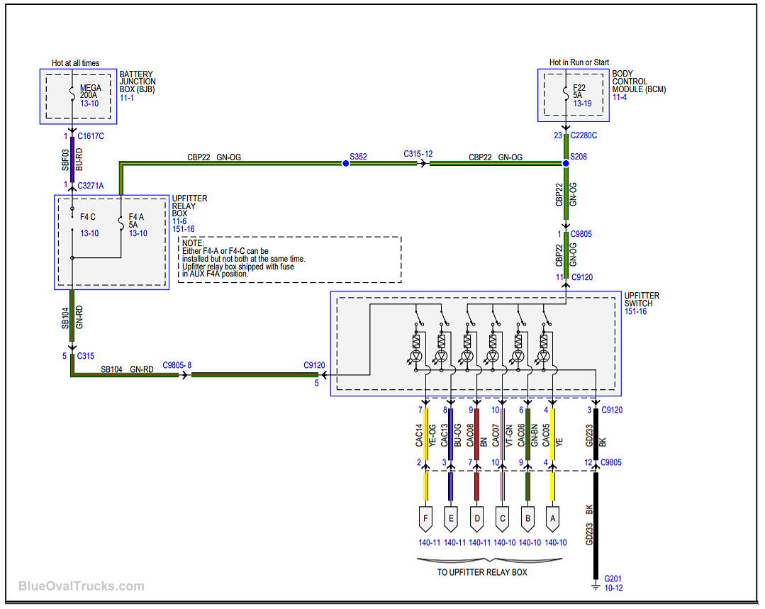
Web While the MSC04316 4-relay harness Figure 4 will function with all BOSS headlight systems the MSC08001 5-relay harnesses Figure 3 will continue to be sold as a spare. Web Locate the upfitter blunt cut wires on the drivers side under the fuse panel in the engine compartment. Web The blue wire shoved into the yellow 20 amp blade fuse is the switched power run for the plow.
Web If you are looking for the installation manual of the RT3 Straight Blade with SmartHitch2 you can download the PDF file from this link. 13 Pin Harness 2020. Electrical System Wiring Schematic Truck Side Electrical System Wiring Schematic Truck Side G10272.
Align the small holes in Blade Shock Mounts 10B with the holes in the center rib of the snowplow as shown in Figure 6.

Youtube

Storks Plows
1
Storks Plows

Youtube

Storks Plows

Storks Plows

Youtube

Youtube

Youtube
Blue Oval Trucks

Youtube

Ebay
2

Youtube

Iteparts Com

2